22 July 2013

New transom takes shape

and puts closure to the hull carpentry.


It's December, 2012.  The Belhaven has a designed length on deck of 19 ft.  The pattern for the top curve of the new transom made from scrap is screwed to the shearlogs at 21 ft., the modified length arrived at after innumerable days of deep contemplation.  Looking back, it now seems to be another proof  of "Two-Footitis," that severe affliction that strikes sailors and boatmen and makes them believe that their present boat would be the ideal one if it were only two feet longer.

My decision is of course based on strictly rational arguments, the best of which is that I want the auxiliary motor inside the boat, not hanging out on a mount off the transom. By their very nature and by the immutable law of Murphy, the motor will quit on you and you will vainly try to revive it by yourself. And this will inevitably happen when the wind and waves toss your vessel around while you are half out over the water bravely fiddling with the motor parts, hoping none of them nor your tools will be forced out of your wet grip this time by Newton's laws of motion.

The least rational argument though possibly the most convincing is that the boat will look lovelier.

The revised plan then is to use make original transom station of 19 ft. into a bulkhead on which to mount the motor and to enclose the motor in a well. A cutout in the transom will allow the motor to tilt up when not in use with very little of it showing outside. By meticulous measurements and estimates the exact additional length needed is--you guessed it--exactly two feet.


With the hull level to the designed waterline, an 18 degree angle is scribed on the side panels inward from the transom top pattern and the sides are trimmed to this line.


The pattern has been replaced by a curved frame. The transom panel is held against this and the sides ...


... to scribe the proper curves for the transom bottom.


After the lower edges of the transom  are cut and positioned, the curves of the bottom panels in turn are traced and trimmed ...


... to get a perfectly shaped and fitted transom.  A small triumph but with an immensely satisfying sense of achievement.


All of which do not perturb a supervisor on the worktable mocking me by resting his head on one of my early miscalculations.


21 July 2013

Working on the longitudinals

stiffens the hull somewhat.


This early in the build you do get to see how the hull looks like once the panels are joined together. But stitch-and-glue is work never done. Or so it seems. You keep going at the exact same place over and over and over: Loose stitch - Adjust - Tighten stitch - Tack weld - Wait for tack to cure - Unstitch - Fillet - Tape 1 - Tape 2 - Tape 3 - Wait for resin to cure - Sand tape edges. 

Meantime the build does not seem to move forward because there's hardly any noticeable change in the appearance of the boat despite all this effort and time. In plank-on-frame boatbuilding, for each construction step there's a palpable progression, a more instantaneous gratification for the effort; you can actually see the boat grow.


To unstitch the keel the hull is hoisted to get enough clearance under. A small butane torch heats stubborn copper wires.  Lemongrass lamp drives away mosquitos.


Stem to stern batten determines new shearline which is 4 to 5 inch higher than that indicated in the plans. Seems to be the best compromise to increase the cabin headroom without making the boat look ungainly.  It should also make for a dryer cockpit. 


After the sides are trimmed, the inwales are glued on with the help of a thousand clamps. Well, almost. Also visible in this photo are the wires tensioned with turnbuckles to keep the bow symmetrical.


The side stringers then go in and a double layer of biax is laminated to the 5mm plywood at the bow. Rather than trimming the cloth at the chines, frugal me decide to run it up all the way up the sides.

Plans indicate diagonal stringers here but other builders of similar design commented that the stringers get in the way of cleaning the area.  


Meanwhile a supervisor appropriates the tool caddy.


The keelson is glued on. Keeping the transom open up to this point makes it easy to get in and out of the hull.


Everything including the kitchen sink is employed to glue down the 5 mm doubler in the cabin section. A fairing compound made of Micromix and fumed silica smooths the biax layers. 

20 July 2013

Positioning the frames

in their places makes one appreciate the size of the Belhaven. 


Because of the planned modifications, temporary frames take the place of the bulkheads. Which turns out to be a good thing because the geometry of the hull after the "butterfly" is opened needs a tweak here and there to make them fit. Stitch and glue is cumbrous and unwieldy for such a large boat.

If-I-knew-then-what-I-know-now:  Should have made well-secured, external cradles at each of the bulkhead stations to help keep all the panels aligned. Too much time is spent checking, leveling, fine-tuning the components that it takes away a lot from actual building. And this has to be repeated before and after every session to make sure no errors get built in.


By end of October 2012:  With a little coaxing all the seams butt neatly and the copper wire stitches are drawn tight.

Encouraged by the the hull going 3D, a lot of work gets done at this time.

The temporary transom frame as situated in the plans straightens out the side panels.


Fitting temporary frames at Bulkhead stations 1 and 2.  Hull interior looks cavernous because the sides are 8 to 10 in. taller than original plan to allow for cutting room should I decide to increase the freeboard.


Bulkhead 3 (with quarter-berth cutout) in position. Original freeboard height is indicated by the horizontal members of the temporary frames.


View of the bow end.


The new transom temporary frame at is positioned 21 ft. with an 18 deg. rake.


By early November filleting and taping of the keel and chines are done. First, fiberglass cloth tapes are cut diagonally from stock under close monitoring by the supervisors doing night duty.


Then masking tape is applied to the outside seams so filleting goo doesn't leak to the floor and stitching wire ends are capped with foam after drawing blood enough times.

The webbing around the hull is hooked up to a chain block at the rafters; the hull can be raised if the keel stitches need to be manipulated.


Finally filleting the inner corners of the joints with a mixture of equal parts fumed silica and wood flour added to epoxy until it's stiff enough not to run. The fillet is then taped over with three layers of fiberglass.

The car batteries are to hold down a slight hump that formed at the junction of the 6mm-9mm scarf when the "butterfly" was unfolded.


19 July 2013

Unfolding the "butterfly"

turned out to be a bit of a challenge--especially when you single-hand it. 


Having a lot of exposed purlins, joists and trusses helps when rigging hoisting blocks.

The assembly is centered in the work area, resting on wooden blocks. The whole length of the keel joint has been loosely stitched at this point. Support posts have been removed on starboard side.


First attempt at opening the "butterfly" proves unsuccessful--the panels are too floppy to hold the shape by themselves despite the support lines. Previous experience of doing this with smaller boats prove inadequate; this is an entirely new adventure.

At 24 ft. the panels are left long to see the feasibility of increasing the hull length from 19 ft. to 21 ft.


Take 2 involves making bottom supports at the bulkheads no 2 and 3 positions.


It's still wobbly but the chines can now be stitched.

Picking up from nine months ago

to post the progress of the build since then.


Hard to imagine how fast nine months slip past. And as has happened in my previous builds, it has progressed in periods of furious activity followed by long stretches of calm.  More pressing matters, unfavorable weather, sometimes inexplicable lassitude would trip the enterprise into a hole and the longer it stays there the more ponderous it is to carry on. Though once the impulse kicks in, the momentum would propel it to a new level.


Early October 2012. Another Ooops! moment upon finding out a mismatch of the bow-end scarfs.


A quick butt joint adds the missing material that will eventually be filleted and taped over.


The offending panel is trimmed to match the correct one and we are back on track.


By late October 2012 the bottom and side panels are assembled into what the Graham Byrnes the designer calls the "butterfly."

The corresponding panels are laid out in the boatshed, stacked together and the bow joint taped.


As per original design, the forward ends of the bottom panels are 5 mm ply (unlike the rest of the bottom panels which are 9 mm) so they are flexible enough to follow a natural bend when the "butterfly" is unfolded.


Keel joint is loosely stitched, temporary braces are screwed on to hold up the side panels and the hoisting lines rigged to blocks at the roof joists.


And up she goes.


One finally gets to see how big this boat is going to be.


The "butterfly" joint at the chine has been reinforced with a small block to take the stress of unfolding.

A length of 1x2 keeps the top edge of the shear at the bow flat. Without it that portion waves like a flag.


01 October 2012

With circumstances and the weather cooperating

a few more steps are taken on this long journey:  


bulkhead #1 mock-up; transom mock-up to act as temporary frame so the new extended transom can be spiled; temporary frame as specified in the plans; and bulkhead #3.  The frame sides are kept long to accommodate the increased freeboard.


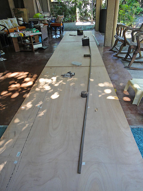
Bottom panels laid out for a final check before gluing the scarfs. 


The starboard bottom panels glued up.


A flaw in the plywood is discovered as the port bottom panels are to be glued together.  Probing with the strip shows the delamination to be only about 4 in. x 8 in. but must be repaired before continuing.


All the joints are scarfed.


16 May 2012

First Cut

As milestones go this marks the confirmation of the commitment.

As the plank outlines are drawn, one gets a good idea of its size.


There is no turning back.  All the bottom planks have been cut.